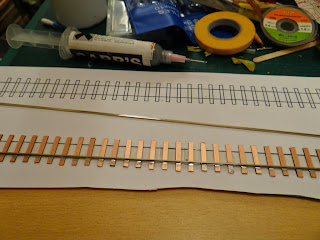
As Paul was kind enough to turn me a set of brass track gauges I no longer have any excuse for not trying to hand build some OO9 gauge track. Paul has already used his gauges to build a working point, but I decided to start with something a little simpler; a 30cm straight piece of track.
Of course, deciding to have a go at making my own track was the easy part, working out which parts I was going to use was a bit harder. The easy part was the sleepers. I'm using 3mm wide strips of copper clad PCB cut to a length of approximately 19.25mm (based on a couple of measurements from some PECO stuff I had kicking around). The rail was a lot harder though. The OO9 gauge track I've bought previously uses code 80 rail. The rails are measured in 1/1000's of an inch, so code 80 is 0.080" high. For a light railway this looks a little on the large side and many people use a lighter rail. For example, Paul used code 55 steel rail to build his point, which is 0.055" high. The problem I had was that I wanted to avoid using steel rail as previous experience shows that it does corrode over time, much more so than modern nickel silver rail. In the end I've compromised and used code 60 nickel silver rail from PECO. This rail (PECO IL-1) is a little odd in that it is designed to be used for either Z gauge (which is really tiny) or as conductor rail in 4mm, but it seems perfect for OO9. C&L Finescale stock both the sleepers and the rail and so an order was placed.
Once the parts turned up the first job was to cut the sleepers. The copper clad PCB turns up in strips the right width (3mm) but 17" in length. Fortunately a razor saw cuts through the PCB easily, the problem is how to cut consistent lengths. I could have just measured the strip and marked it up, but I decided I'd make up a little jig to aid the process. This jig sits nicely in my small mitre box and when pushed up against the blade of the razor saw ensures a consistent sleeper length. Once I'd cut a couple of strips into separate sleepers, I then turned to building the track.
I started by drawing up a template on the computer to aid in positioning the sleepers and rails. This was easy for a straight section, but if want to build more complex track in the future will need a little more thought. The sleepers were then stuck to the template using double sided tape, and then the first rail was soldered in place, using coffee stirrers to hold it down while I applied the soldering iron. Once the first rail was soldered to every sleeper I could move on to the tricky bit of adding the second rail.
It turned out that with the track gauges Paul had made me, and some more coffee stirrers, fitting the second rail was nice and straightforward and before long I had something that actually looked like a piece of track. Even better a quick test with a wagon and it looked like it might actually work too. What I'd forgotten to do though was to file a gap into each sleeper to ensure that the rails weren't electrically joined. Fortunately on the straight track it was fairly easy to get a file in between the rails to remove some of the copper; in the future I'll definitely be doing this before I solder the rails down. Finally I removed the track from the template, soldered a wire to each rail and then had a go with letting an actual locomotive run along the track.
I opted to try it out with the small diesel I built from the Narrow Planet kit, as the motor would be a lot easier to replace if everything went wrong than it would on the Quary Hunslet, but fortunately, as you can see, it all worked perfectly. In it's current form the track isn't going to win any beauty contests but it should clean up nicely and now I know that I can at least build plain track which is useable so I'll call that success.
 As
As 


Spot on and drop dead perfect.
ReplyDeleteI know near enough isn't good enough but I was warm.
DeleteYou were very close, and I did think about producing something similar to help space the sleepers/rail but decided that plastic plus soldering iron probably wouldn't work too well. Well done for the closest guess though!
DeleteVery nice Mark, it sure beats the stuff produced down in Devon!
DeleteThanks Geoff. I'm glad I'm not the only one who thinks it looks better than the PECO stuff, even if it is a little coppery coloured at the moment. The next step will be to fill the gaps and then try and apply some colouring of some form, so hopefully it will look even better soon.
DeleteI've built a fair number of PCB points over the years Mark and used to spray them in red or grey primer once the gaps had been filled. After cleaning the rail tops the sleepers and rail were picked out in colours to suit but I always avoided the so called 'rust' as I think light/dark earth works better.
DeleteNice job Mark, and I'm pleased that the gauges were of use. I may steal the jig idea, I like simple things that work.
ReplyDeleteDefinetely better than Pritchard's Silly Track, which looks really odd with small wagons perched on its huge section rails...
Iain Rice's 'A Pragmatic Guide to Building, Wiring and Laying PCB Track' (phew!) is my current bedside reading, worth a look.
It's a shame I'll never use all this knowledge I'm acquiring. I still find it fascinating though.
ReplyDelete